FAQ
HYPACKに関する質問
18.ドレッジパック---浚渫管理プログラム(Dredgepack®)
ID.Q18-3
Q. バックホーの利用(Dredgepack on a Backhoe)[英語]
A.
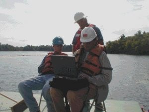
Recently an installation was performed on a backhoe running Dredgepack® with a RTK GPS. The backhoe has a rigid pole attached to the bucket. This bucket is being used to remove material from a lake. The requirements of the removal are to remove a fixed depth of material from a set area. This seems a bit confusing at first. The customer wants to remove 2 feet of material from the lake. Since most dredge operations that I have been involved in remove material to a template, this was a bit different.
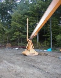
To begin the project, let's start with the GPS configuration--the most important aspect of setting up the job. The customer is using an RTK system with a pre-established base station. On the backhoe, the GPS antenna is mounted to the bucket by the pole as displayed in the figure to the right. A long cable is run the length of the boom arm to the GPS receiver in the cab. The initial configuration of the RTK was very simple. Since the job site is a relatively small construction site, the datum to ellipsoid separation was entered into the antenna offsets. Once the system was communicating properly, we checked the Hypack® elevation by setting the bucket at the water surface and comparing the elevation in Hypack® with the elevation of the lake surface. The result was a perfect match! It is sure nice when the numbers work out.
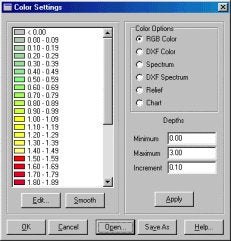
After the GPS was up and functioning, the rest of the job was simple. To show the location of the material removed we use a Matrix. The Matrix file is comprised of a rectangle divided up into cells 3 ft by 3 ft. The bucket was measured to be 3 ft by 5 ft. This was to allow us an overlap to ensure all of the material was removed. Using the Matrix in Dredgepack with the Display Difference option, the operator can then monitor the elevation of bucket and removal a set amount of depth. The Matrix colors are set to the range of material we are removing and not the value of the elevation. Our lake elevation was 108.75 ft.. Our colors were set as they are in the image to the right. The operator stops digging when the cell is Red.
Now for the part where something went wrong. The GPS, being mounted so close to the boom, occasionally switched to RTK Float from a Fixed signal. This caused the position and depth to change drastically. After a few seconds, the Fixed RTK would be regained and the system would function properly again. The problem was that while we were updating the Matrix, the cells would fill with bad position and depth. This was due to the fact that we were not using the RTK for tide, but as an echo sounder. Had we been using it for tide, the problem could have been removed in post-processing. To find the problem required a trip to the site by Lazar. Fifteen minutes into Lazar's visit the problem was solved and we were on our way to an early lunch. ( Just kidding Pat! We were working very hard.)
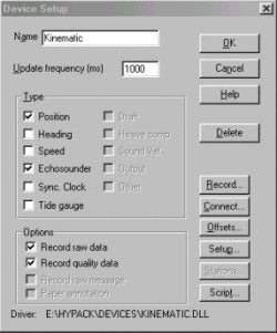
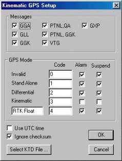
After returning to the office, a change was made to the Kinematic driver to allow the user to suspend logging where the position is less than Kinematic. The position will continue to update the data display and boat location, but no elevation or depth will be returned. This allows the user to continue to see where they are, but not to receive bad tide or depth readings that must be corrected later. This is done through the checkboxes in the GPS Mode section of the driver setup dialog. The figures below show the device setup dialog (left) and driver setup dialog (right) with the correct settings for this situation.