FAQ
HYPACKに関する質問
13.ボリューム---体積計算(Volumes)
ID.Q13-18
Q. フィラデルフィア法体積計算2(Explanation of Philadelphia Volume Summaries)[英語]
A.
I recently was asked by a user what all of the different items that were included in the Philadelphia Post-Dredge Volume Summary meant. It took me a couple of minutes to figure it out, even though I work with it about every other week. I figured it would be good to run a test example and explain some of the output.
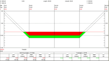
Step 1: 8.5m Data Set in Philadelphia Pre-Dredge
I first created two test data sets that would create a set of data at 8.5m and 9.5m across my survey lines.
My first data set and the associated cross section template are shown in the figure to the right.
The template points are as follows:
| Distance | Depth |
|---|---|
| 0.0 | 0.0 |
| 50.0 | 10.0 |
| 100.0 | 10.0 (Centerline) |
| 150.0 | 10.0 |
| 200.0 | 0.0 |

All of the depths in the first data set are at 8.5m. There are ten parallel lines.
I first ran the volumes for this data set using the Philadelphia Pre-Dredge method. This generated the report shown to the right:

The Left Slope and Right Slope areas are reported as 5.63 m2each. This is correct as shown in the figure below.
The area for the Left Channel and Right Channel is simply the height times width (1.5 x 50) and the 75 m2 shown in the report is correct.
Since each section is identical, the volume is equal to the sum of the area under each section (161.25² ) multiplied by the distance between sections (100) giving 16125.00 m³.
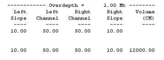
The overdepth template was placed one meter below the design template. The results from the volume report are shown in the figure right.
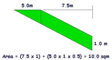
The left slope area is identical to the right slope area and is shown in the figure below. The volume is shown to be 10m², which is identical to that shown in the CROSS SECTIONS report.
The overdepth in the Left Channel and Right Channel is equal to the depth of overdepth template beneath the design template (1.0m) times the distance (50m) which is 50m².
The area between two sections is equal to the average area under a section (120m; they are identical sections) times the distance between sections (100) resulting in 12,000 m³ which is the volume shown in the report.

The results for the channel (nine pairs of lines) are shown in the figure to the right.
The Total Material To Project Depth is total volume of material located above the design template. This is equal to our area per section above the design template (16,125 m³) times the number of pairs of lines (9) and is exactly correct.
The Total Allowable Overdepth is the total amount of material located between the design and overdepth templates. This is equal to our volume per section (12,000 m³) times the number of line pairs (9) = 108,000 m³. Once again, the CROSS SECTIONS program is exactly correct.
The Total Pay Place is simply the sum of the two items above.
Step 2: 9.5m Data Set in Philadelphia Pre-Dredge
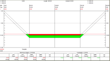
I next created a new data set, using the same template, but changing all of the depths to 9.5m. A typical section is shown in the figure right.

The design material is shown in the figure right. I’ll leave it to you to prove the areas and volumes are correct. [Trust me, they are.]
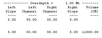
The overdepth material is shown in the figure right. Once again, feel free to verify that the areas and volumes are correct. [They are.]

Finally, the volume summary from the Philadelphia Pre-Dredge report is shown in the figure to the right. All values are correct and now we are ready for the BIG test.
Step 3: 8.5m and 9.5m Datasets in Philadelphia Post-Dredge Method.
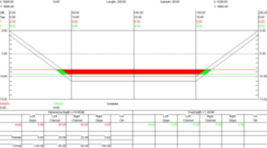
Finally, I entered both the 8.5m dataset (PreDredge) and my 9.5m dataset (PostDredge) datasets into the Philadelphia Post-Dredge Method and examined the results. A typical cross section is shown in the figure right.
Notice that the program now colors the material removed, not the material remaining. This is something that confuses a lot of users.
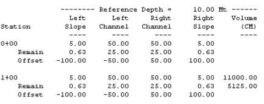
The results for the first two sections are shown in the figure to the right.
The “Area” shown in the report is the area of material removed in that section. Note that it is possible to get a negative area for a segment if the area computed from your post-dredge survey is greater than the area from your pre-dredge survey.
| Left Slope | Left Channel | Right Channel | Right Slope | |
|---|---|---|---|---|
| 8.5m Area | 5.63 m² | 75.00 m² | 75.00 m² | 5.63 m² |
| 9.5m Area | 0.63 m² | 50.00 m² | 50.00 m² | 0.63 m² |
| Material Removed | 5.00 m² | 25.00 m² | 25.00 m² | 5.00 m² |
The Remain areas are generated from the 9.5m data set and are identical to those computed when we ran the Philadelphia Pre-Dredge volumes for that data set.
The volume for the first section (11,000 m³) is the same value achieved by taking the volume for the 8.5m data set (16,125 m³) and subtracting the volume from the 9.5m data set (5,125 m³). The same is true for the Overdepth areas and volumes.
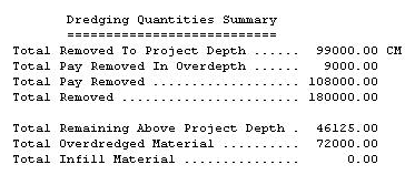
The summary for the Philadelphia Post-Dredge Volume Report is shown above. The values are explained as follows:
Total Removed To Project Depth: This is the difference between the volume (above design template) computed for the Pre-Dredge data set (145,125 m³) minus the volume computed for the Post-Dredge data set (46,125 m³). Note that this can be a negative number if there is more material present in the Post-Dredge survey!
Total Pay Removed in Overdepth: This is the difference between the volume of material contained in the area between the design and overdepth templates for the Pre-Dredge data set (108,000 m³) minus the volume for the same area in the Post-Dredge data set (99,000 m³).
Total Pay Removed: This is the sum of the Total Removed to Project Depth and the Total Pay Removed in Overdepth.
Total Removed: This is the total material difference between the Pre-Dredge survey and the Post-Dredge survey without regard to the design and overdepth template. In our example, the survey area covered a 200m x 900m area (180,000 m²). We changed the surface from 8.5m to 9.5m, taking away 1m of material. Multiplying the area (180,000 m²) by the height (1m) gives us 180,000 m³, representing the Total Removed.
Total Remaining Above Project Depth: This is the remaining material above the design template from our Post-Dredge survey. It is independent from the Pre-Dredge survey surface and represents how much material you have to remove to get the channel down to the project design.
Total Overdredged Material: This represents the material that has been removed beneath the overdepth template. It is computed by taking the Total Removed (180,000 m³) and subtracting from it the Total Pay Removed (108,000 m³). In our example, this results in an answer of 72,000 m³.
Total Infill Material: This is the volume of material where the Post-Dredge survey is deeper than the Pre-Dredge survey. In our example, we have no such area and the result is 0.00 m³.