FAQ
HYPACKに関する質問
14.ティンモデル---3次元成果(TIN Model)
ID.Q14-13
Q. 最新のDXF出力機能について[英語]
A.
The TIN Model program has a new routine for exporting DXF files. While maintaining most of the features of the previous routine, it has a few new features and has become a bit easier to use. You can:
Create labeled contour lines in 1-step instead of creating the lines and labels separately.
Customize contour colors more easily than before. This color scheme is separate from HYPACK® or TIN Model color schemes.
Add weight or texture to a lines to help distinguish them from neighboring contours.
Let’s take a look at how it works and look at these improvements as we go. (We can work from the Sample_Monepts project file, if you have the 2003 HYPACK® Training Conference CD.)
Launch the TIN MODEL program and create a simple TIN to Level model.
Original TIN Model
Access the DXF EXPORT routine in the same way as before, by selecting EXPORT-DXF FORMAT from the TIN MODEL menu.
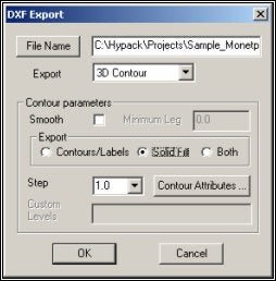
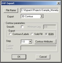
Set your options for the DXF file to be created.
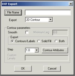
The new DXF Export dialog includes most of the features previously available though you may see them in a slightly different form.
Name the DXF file to be created as you did before. Just click [File Name] and enter the path and name.
The Export Mode is selected from a drop-down list, just a minor change from the former radio buttons.
Note: 3D files only appear in three dimensions when you load them to a CAD program. In HYPACK® MAX, they are viewed from above and appear only 2-dimensional.
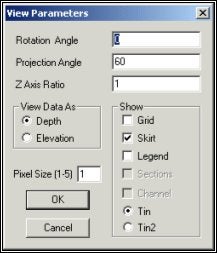
In the previous version of DXF Export, Export Object was selected in this dialog. This selection is now made in the view options dialog.
Most often, you would select TIN. The TIN2 option might be used if you have done a TIN to TIN calculation. In this case, TIN will draw from data in the Input File and TIN2 will draw from the data in the Second File as specified in the Initial Data dialog of the TIN MODEL program.
The Contour Parameters area is where the most significant changes have been made.
Smooth enables you to create smoothed contours. It creates a DXF file about ten times the size of the non-smoothed contours. These smoothed contour s can not be plotted from the (older) HYPLOT program. They can be plotted from HYPLOT MAX or from other CAD packages so, if you want to plot smooth contours, you will need a printer that is up-to-date enough to handle it. (Basically, that’s anything other than an old pen plotter.)
The Minimal Leg limits the amount of smoothing. Smoothing will not occur where the TIN Model leg is shorter than specified here. (This option hasn’t changed!)
Export defines exactly how much data should be included.
Contours/Labels creates contour lines and, if specified in the contour attributes, labels for them.
Solid Fill creates color-filled contours.
Both overlays contour lines on color-filled contours.
Step enables you to specify a regular contour interval, used in the creation of 2D and 3D Contours. If you desire an irregular step, click on [Other] then enter your desired contour levels in the Custom Levels field. Leave a single space between each contour level. For example, “2 5 25 100". (This option has only been changed to a drop-down box from radio buttons.)
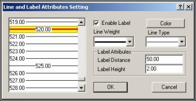
Once you have the contour parameters set, click [Color Attributes]. The Line and Label Attributes dialog will appear. Each contour level is shown at the left according to the depth range of your data and the Step specified in the previous dialog.
Line and Label Attributes Dialog
You can select one or more of them then, quickly and easily, make selections at the right to set their attributes. The display on the left shows how each contour line will appear in the exported file.
To select several individual contour lines, hold the Ctrl key while you use your mouse to choose your lines
To select a range of contour lines, hold the Shift key and select the first and last line of a range.
Enable Label places labels on the selected contour according to the Label Attributes where:
Label Distance defines the distance, in survey units, between the labels on each contour.
Label Height sets how big the label will be.
Line Weight offers a choice of increasing thicknesses for you to accentuate certain contours.
Line Type provides five options, solid line and four combinations of dots and dashes for further distinction from other lines.
Note: Windows® can not handle both line type and weight. Therefore, in any Windows® application, including HYPACK® MAX, contours that have been given both a dotted line type and a weight thicker than 1 pixel, will appear solid. They will, however, be drawn with both type and weight characteristics if you import them into a CAD package.
In this example, we have created contours every foot (or meter depending on your survey units) and every 10th contour is accented with a weighted red contour line. Also, every 5th contour is labeled at 50 foot (or meter) intervals along its length with numbers 2 feet (meters) tall.
When you have finished specifying contour attributes, click [OK] to return to the DXF Export dialog.
Click [OK] again to create the DXF file. You will see the file drawn to the TIN screen.
It will be saved to the specified place and File Name ready to be loaded to HYPACK® MAX as a background file or to any other package that uses DXF format files.
Resulting DXF File drawn to HYPACK® MAX screen
In this example we created 2-dimensional,
labeled contour lines.
With one or two simple changes in the DXF Export dialog,
we can make it 3-dimensional file or
a solid fill contour.
Close up View of Resulting DXF in HYPACK® MAX
Change the Export Contour Parameter to “Solid Fill” and the lines and labels are replaced by a color-coded solid image.
Solid Filled Contours
Change the Export Contour Parameter to “Both” and the labeled contour lines are superimposed on the solid fill model.
Smoothed, Solid-filled, Labeled Contours