HYPACKに関する質問
18.ドレッジパック---浚渫管理プログラム(Dredgepack®)に関するFAQ
Q新しいデバイスドライバ(New Device Driver for Dredgepack®)[英語]
FAQ ID:Q18-1
The latest device driver for Dredgepack® was developed due to the need for a device that can be used to reference a position relative to a boat origin. This sounds confusing but it really is quite simple. In dredging terms the new device allows you to reference the position of the spud. By setting in the offsets from the boat reference point you can create a separate mobile that will give you position and distance from the center line of the spud. This is a critical piece of information when positioning a cutter suction dredge on a planned cut. By creating a center line the dredge operator can then use the spud XTE to ensure that the dredge is positioned properly.
Image 1
In Image 1 I have used the device to position 4 spuds, a crane pad and a working trailer on a barge. As the barge moves and rotates the objects onboard remain positioned properly. This should allow the user to create complex shapes to be displayed for easy reference.
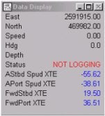
Image 2
The nice advantage of this new device is that the XTE can be displayed in the data display. On the shape I have a large dark blue square positioned where the crane pad is located. I have also added a smaller dark blue rectangle to show the location of the operators trailer. The four small light blue squares are positioned where the four spud holes are located.
In Image 2 I have captured the data display showing the reference to the four XTE values. This can be done for the X and Y of the spud also to allow exact positioning of an object for other applications such as position monitoring of a barge once it has been anchored. I believe that this new device driver will be very useful in the future applications of Dredgepack®. If you have specific questions regarding this device please e-mail me at jerry@coastalo.com.
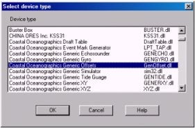
Image 3
Configuration of the GenOffsets driver.
The GenOffsets driver is a HYPACK® / Dredgepack® MAX device. This driver is used to reference a position as described in the previous document. The following description should allow you to add this driver to your hardware and use the device.
In the Hardware program you should select the Devices menu item and Add a Device. The Select Device Type window (Image3) will appear. In the list of devices you will then select Coastal Oceanographics Generic Offsets driver. This will load the device.
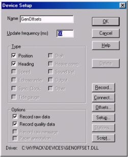
Image 4
The next screen (Image 4) is the device setup. The only options for this device are Position and Heading. The Heading box must be checked to allow the device to steal its heading from the main vessel. If you notice that the second shape does not rotate exactly with your main shape but lags a small amount this box is most likely not checked. I recommend setting the Update Frequency to the same rate as the positioning device. In the Record menu I recommend selecting the record option to never unless you are interested in recording the position of the device. For a spud you might want to set the record option to a predetermined number of seconds. This configuration will allow you plot out the location of the spud as it traveled through the cut. Also this will allow the plot to show the swing in relation to the spud position.
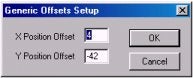
Image 5
Under the Setup option the button there is a X Position Offset and a Y Position Offset (Image 5). These offsets are used to locate the new item in relation to the reference point of the main vessel shape. The position referred to during this step is corresponding to the reference point of the shape you have created for your spud or other object.
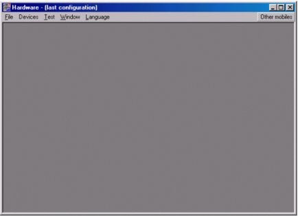
The other important item to be completed in the Hardware program is to add this item as a Other Mobile. On the far right menu of the Hardware program is a option for the Other Mobile. To explain, the Other Mobile idea. A Other Mobile is a separate vessel displayed on the Map in the Survey / Dredgepack® program. This also allows you to display the parameters of the other mobile. Such as the X and Y of the mobile. Below is an image of the Hardware program.
Harware Program
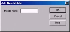
Once you have selected the Other Mobile the next option to choose is Add. This brings up the following menu. Name the new mobile and then select Ok.
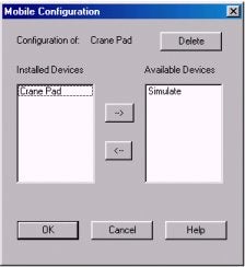
The next thing we want to do is to add our devices to the mobile. The image to the right is the Mobile Configuration menu. To reach this menu you need to select the Other Mobile button and then select the mobile name you entered. Using this menu you can add the devices to your mobile. This can include any device types that you would be using on the main vessel. In our application this is going to be the device we setup previously. I named my device Crane Pad. This refers to the location of the Crane Pad on the barge. To add a device to a mobile you first select the device in the box on the right labeled Available Devices. Once you have selected the device you select the arrow button sending the device to the list on the left labeled Installed Devices. This moves the available device to the mobile. All of the devices listed are then associated with the new mobile. If there is an echo sounder or other device the position is calculated using the position of the mobile and the offsets associated with the hardware.
In the Survey program you will now see two shapes. Using the new device you should right click on the main vessel and de-select the display shape. Once this is accomplished you can then right click on the second shape to select shape. Select the shape you would like to display. Once you have the new shape on the screen you should right click on the main vessel and select display shape. This will redraw your main vessel. As I showed in the original document there are many uses for such a driver. I hope that you have as much success with this driver as I have had.
QDregepackとSurveyプログラムにおけるマトリックスオプション(Matrix Options in Dredgepack® and HYPACK® Max Survey)[英語]
FAQ ID:Q18-2
New Options:
A couple of new options have recently been added to the Hypack® Survey and Dredgepack programs that may interest you. The one that is particularly interesting to me is found in the Matrix Options dialog in each program. In the past, the matrix data has been updated whether you were online or offline. Now you have the option to choose when data will be entered to the Matrix.
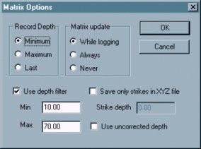
The Matrix Options Dialog
The Matrix Update option enables you to choose when soundings will be drawn to the matrix.
- While Logging paints the matrix only while you are online. This will enable the matrix data to coincide with the survey data.
- Always paints the matrix whether you are online or not (as before). This option enables you to follow your dredging in the Matrix while not recording the Raw data if you don't need it.
- Never tells the program not to update the matrix. You can display the matrix without changing the data.
The Use Uncorrected Depth is a new option requested by one of our users. Very simply, gives you the choice to store raw depths or corrected depths to your matrix.
Depth Mode vs. Elevation Mode
As I was working on the documentation for these changes and reviewing how these systems all work together, it was clear that the Elevation Mode option in the Matrix menu could be a source of confusion. Here are a couple of places that might trip you up.
Save only strikes in XYZ file determines what is saved when you select MATRIX-SAVE TO XYZ. You can elect to save the depth as the z-value.
- Depth is recorded when this option is unselected--all depths will be saved.
- Strike Depth saves the difference between the sounding value and the strike depth only where the soundings are greater than the user-defined strike depth. If the sounding is deeper than the strike depth, no value is saved at that cell. This is useful to see how much must be dredged to level the area to the strike depth.
Beware!This function is affected by the Elevation Mode setting. If you are in Elevation Mode, this will record depths deeper than the strike depth. Probably not a very useful set of data!
The Use Depth Filter option is unaffected by the Elevation Mode. You may get confused though, since the rest of Hypack Max reverses the sign of the depth reading when it is set to elevation mode. Survey and Dredgepack do not invert the Z value of the soundings so all of the values are positive.
If you choose to use this option, in either mode, use positive numbers to specify your range.
The Record Depth option is also affected by the mode. In this case the minimum and maximum depths values will reverse meaning as follows:
The "Minimum" option will record the smallest depth value received in that cell.
- In Depth Mode, the smallest value is at the shoalest point.
- In Elevation Mode, the smallest value is at the deepest point.
The "Maximum" option will record the largest depth value received in that cell. - In Depth Mode, the largest depth is deepest, while the smallest depth is shoalest.
- In Elevation Mode, the largest depth is shoalest, while the smallest depth is deepest.
The "Last" option last sounding received. It is the same regardless of mode.
Qバックホーの利用(Dredgepack on a Backhoe)[英語]
FAQ ID:Q18-3
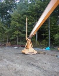
Recently an installation was performed on a backhoe running Dredgepack® with a RTK GPS. The backhoe has a rigid pole attached to the bucket. This bucket is being used to remove material from a lake. The requirements of the removal are to remove a fixed depth of material from a set area. This seems a bit confusing at first. The customer wants to remove 2 feet of material from the lake. Since most dredge operations that I have been involved in remove material to a template, this was a bit different.
To begin the project, let's start with the GPS configuration--the most important aspect of setting up the job. The customer is using an RTK system with a pre-established base station. On the backhoe, the GPS antenna is mounted to the bucket by the pole as displayed in the figure to the right. A long cable is run the length of the boom arm to the GPS receiver in the cab. The initial configuration of the RTK was very simple. Since the job site is a relatively small construction site, the datum to ellipsoid separation was entered into the antenna offsets. Once the system was communicating properly, we checked the Hypack® elevation by setting the bucket at the water surface and comparing the elevation in Hypack® with the elevation of the lake surface. The result was a perfect match! It is sure nice when the numbers work out.
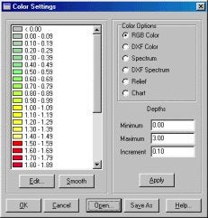
After the GPS was up and functioning, the rest of the job was simple. To show the location of the material removed we use a Matrix. The Matrix file is comprised of a rectangle divided up into cells 3 ft by 3 ft. The bucket was measured to be 3 ft by 5 ft. This was to allow us an overlap to ensure all of the material was removed. Using the Matrix in Dredgepack with the Display Difference option, the operator can then monitor the elevation of bucket and removal a set amount of depth. The Matrix colors are set to the range of material we are removing and not the value of the elevation. Our lake elevation was 108.75 ft.. Our colors were set as they are in the image to the right. The operator stops digging when the cell is Red.
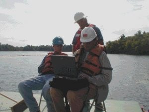
Now for the part where something went wrong. The GPS, being mounted so close to the boom, occasionally switched to RTK Float from a Fixed signal. This caused the position and depth to change drastically. After a few seconds, the Fixed RTK would be regained and the system would function properly again. The problem was that while we were updating the Matrix, the cells would fill with bad position and depth. This was due to the fact that we were not using the RTK for tide, but as an echo sounder. Had we been using it for tide, the problem could have been removed in post-processing. To find the problem required a trip to the site by Lazar. Fifteen minutes into Lazar's visit the problem was solved and we were on our way to an early lunch. ( Just kidding Pat! We were working very hard.)
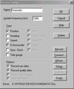
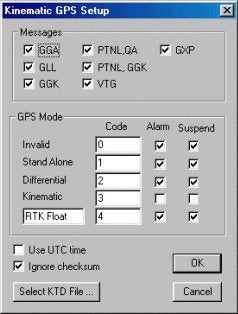
After returning to the office, a change was made to the Kinematic driver to allow the user to suspend logging where the position is less than Kinematic. The position will continue to update the data display and boat location, but no elevation or depth will be returned. This allows the user to continue to see where they are, but not to receive bad tide or depth readings that must be corrected later. This is done through the checkboxes in the GPS Mode section of the driver setup dialog. The figures below show the device setup dialog (left) and driver setup dialog (right) with the correct settings for this situation.
Qマトリックス表示オプション(Display Options for Matrix Files Used in Dredging)[英語]
FAQ ID:Q18-4
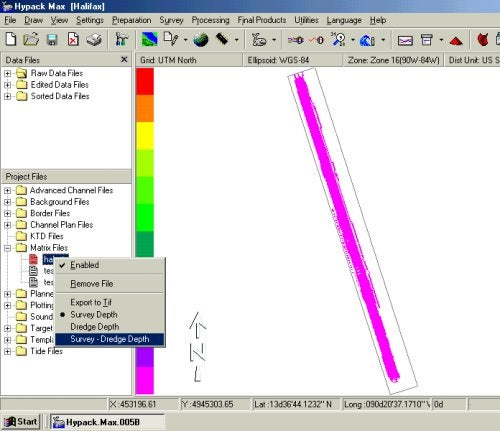
Most users view Matrix files as two dimensional objects, that is as a (row x col) grid. A third dimension, the Depth, is contained inside each cell of the matrix. The matrix structure also has the capability of storing an additional depth for each cell, which gives a stacking of depths projecting from the surface of the screen. This feature is used in Dredgepack® for recording the pre- and post-dredging depths of a given area. You can display the Survey Depth, the Dredge Depth or the Difference between the two depths (Survey-Dredge Depth) in Dredgepack® by selecting it through the Matrix menu.
There is a new option in HYPACK® Max that supports this display in the main Max window. Users with a Dredgepack® or Universal key can select which depth to view by right clicking on Matrix Files in the Project Files list and selecting the appropriate option from the menu. If the cell is missing either the Survey or Dredge depth, then the cell will display blank in the difference mode. The screen capture below gives an idea of how it works.
Q浚渫船の表示機能について(Dredgepack Shapes in the Profile Screen)[英語]
FAQ ID:Q18-5
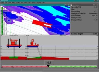
A recent development in Dredgepack is the ability to show the shape of the vessel in the Profile window. This image (right) was captured during a recent visit to the Dredge George McWallace. There are several items displayed here. In the Profile there are two sections. The section to the left is the view looking forward through the dredge. The arm of the suction is displayed. In this case the suction was a 30 foot wide dustpan dredge. The section to the right is the view looking across the path of the dredge or perpendicular to the vessel. In the perpendicular view the operator has the ability to see what material is ahead of the dredge.
The distance that is viewed in these windows are set by the operator in the Profile window setup menu.
In the next image we have a Degroot Cutter Dredger CZ 400. The plan of the dredge was scanned and forwarded to Coastal Oceanographics. The image was taken and cleaned so that small details are removed. This is because in a large drawing a small detail is nice but when the image is reduced to the size drawn below, the detail makes the image appear blurred. As the image below shows, enough detail was left to make the dredge readily identifiable to anyone that has worked on this type of dredge.
Also the plans of an Ellicot 370 were sent as part of a current project. This is the image from the Ellicot dredge. Most of the detail is removed to make the image appear clean and then colored in to enhance the display.
To change the image that is displayed in the Profile window the user is required to modify a configuration file. Configuration files are also known as ini files. This should sound familiar to anyone that has used an earlier version of HYPACK®. HYPACK® Max 2.12 includes a shapes folder where the BMP images and the associated configuration files are stored. Included in the shapes folder are images for the Default shape, Degroot dredge and an Ellicot 370. The current version of Dredgepack supports several items in the Profile window for the differing types of dredges. It is possible to show the Cutter Suction, Hopper Left, Hopper Center and Hopper Right. For every mobile with depth the user has a Profile window. That is why there are so many Hopper displays.
The next display is the Profile setup. The items on this display have been highlighted to show what applies to the Profile view.
The Paintshop Pro program was used to modify the shape image. Any graphics program that works with bitmaps can be used. The nice part of Paintshop is that the actual pixel position of the cursor is displayed. This is important for modifying the configuration settings.
A sample of the data that is stored in the configuration file is shown below. This data is modified to properly display the shape in the window. The same data is in the configuration file for the perpendicular and forward looking files. The file to modify the perpendicular view is the …prof.ini file and the forward view is the …cross.ini file. The "…" should be the cutter or hopper as the case may be.
Level is the water level on the image. This is where 0 will be.
Arm X is the distance from the left edge of the bitmap in pixels to the point the arm attaches.
Arm Y is the distance from the top edge of the bitmap in pixels to the point the arm attaches.
BMPFile is the image to display.
By modifying these items the Profile window can be adjusted to display a custom shape corresponding to any dredge.
[General]
LEVEL=120
ARMX=280
ARMY=120
BMPFILE=c:\hypack\shapes\Degrootprof.bmp