HYPACKに関する質問
4.ハードウェアのセットアップ(Hardware)に関するFAQ
QCom(RS-232Cシリアル)ポートチェック(Com Port Check)
FAQ ID:Q4-1
COM PORT CHECK
HYPACKのI/O Test、またはSurvey Programでデバイスが正しく動いていないと思われる時、新しいデバイスでそのフォーマットが分からないときがあるかもしれません。その場合は以下の手順を踏んでください。
始めに行って欲しい事は、Device/hardwareのTestと、PCのコムポートテストです。
そうすれば、デバイスがどのようなメッセージを出力しているか確認できるはずです。
もし、何もメッセージが画面上に表示されなければ、それはHYPACKの問題ではなくて、デバイスの故障、デバイスの設定、ソフトウエアの設定(デバイスは9600 Baudで送っているのに4800 Baudで受信している)等の問題があります。
以下テストの手順です。
Windows 3X
アクセサリーディレクトリをクリック
TERMINALをクリック
メニューバーからSETTINGをクリック
SETTINGメニューからCOMMUNICATIONSをクリック
使用しているデバイスの出力とこの設定を同じにする
OKボタンをクリック
TERMINALはデバイスが送るデータを表示します
Windows95
STARTをクリック
PROGRAMSをクリック
ACCESSORIESをクリック
HYPERTERMINALをクリックHYPERTERMINAL.EXEをクリック
NAMEフィールドに適当な名前を入力
OKボタンをクリック
CONNECT USINGフィールドを使用するポートを指定する
OKボタンをクリック
使用しているデバイスの出力とこの設定を同じにする
OKボタンをクリック
HYPERTERMINALはデバイスが送るデータを表示します
注意:この手法ではCOM1~4までしか使用できません。
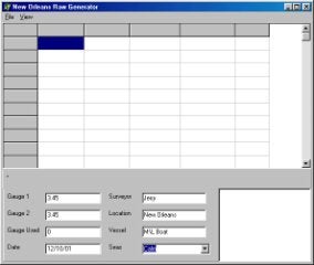
Qオートマチック喫水補正用ドライバ(Automatic Draft Device Driver)
FAQ ID:Q4-2
通常、船はその船速によりドラフト(喫水線)量が異なります。正確な測量を行うには、測量中のドラフト量の記録を行う必要があります。つい最近ま で、船速をモニターし、そして、ドラフトが変化した時期を決定することが測量士にとって必要であった。そして、測量士は、測量プログラムの中でドラフト量 をマニュアルで変える必要がありました。
HYPACK MAXではこのドラフト量を自動的に更新することができます。
ただし、このデバイスドライバを使用する場合、あなたは、ドラフトテーブルドライバを選択する必要があります。
このデバイスドライバのコンフィギュレーションを行うためには、Draftがチェックをチェックします。このデバイスドライバはシリアルポートの設定の必要性はありません。ただし、それ以外の設定は必要になります。
このデバイスドライバを使用するには表中の船速と対応するドラフト量を入力してください。
以上ですべての設定は終了です。
Q自動追尾トータルステーションの利用(Geodimeter ATS 600)
FAQ ID:Q4-3
ダムなどでGPSが使用できない現場においてHypackMAXではライカ社、トリンブル社製自動追尾トータルステーションが使用可能です。
設定
メニューよりHardware-HypackHardwareを選択し、Hardwareプログラムを起動します。Device-AddDeviceを選 択しトリンブル社製自動追尾トータルステーションの場合は"GEODMET2.dll"を選択します。ライカ社製自動追尾トータルステーションの場合 は"Leica.dll"を選択します。トータルステーションではXYZデータを出力するように設定します。
Surveyプログラムでは緯度、経度の欄にXYの値が表示されますが、問題ありません。ただしトータルステーションの機械点座標は適切に設定してください。I
Craig Berry testing the Geodimeter ATS 600 Driver
QGPSの精度比較(GPS Error Specifications--A Comparison of Terms)
FAQ ID:Q4-4
GPSの精度の表現方法がいくつか存在します。3mCEPと表記されている場合、データの50%が3m以内に含まれるということになります。
GPSエラープロバビリティは標準偏差のk倍によって与えられる以下の式によってえられます。
以下の表はエラーの相対関係を示します。
| Name | Probability | k | 1 | 2 | 3 | 4 | 5 | 6 | 7 | |
|---|---|---|---|---|---|---|---|---|---|---|
| 1 | 1-sigma (standard ellipse) | 39.35% | 1.000 | 1.00 | 1.18 | 1.41 | 2.00 | 2.45 | 2.83 | 3.00 |
| 2 | Circular Error Probable (CEP) | 50.00% | 1.177 | 0.85 | 1.00 | 1.20 | 1.70 | 2.08 | 2.40 | 2.55 |
| 3 | Distance RMS (DRMS) | 63.21% | 1.414 | 0.71 | 0.83 | 1.00 | 1.41 | 1.73 | 2.00 | 2.12 |
| 4 | 2-sigma ellipse | 86.47% | 2.000 | 0.50 | 0.59 | 0.71 | 1.00 | 1.22 | 1.41 | 1.50 |
| 5 | 95% confidence level | 95.00% | 2.448 | 0.41 | 0.48 | 0.58 | 0.82 | 1.00 | 1.16 | 1.23 |
| 6 | 2 DRMS | 98.17% | 2.828 | 0.35 | 0.42 | 0.50 | 0.71 | 0.87 | 1.00 | 1.06 |
| 7 | 3-sigma ellipse | 98.89% | 3.000 | 0.33 | 0.39 | 0.47 | 0.67 | 0.82 | 0.94 | 1.00 |
Q方位検出のための2つのGPSの使用(Using a Second GPS for Heading)[英語]
FAQ ID:*Q4-5M
The otfgyro.dll is a custom device driver that first appeared in Hypack 8.9. The otfgyro.dll, when used in conjunction with the nmea.dll, will calculate heading when using two GPS receivers that have their antennas mounted fore and aft of the vessel. This method is often preferred on dredges and barges.
The nmea.dll is used with one GPS to calculate position, and should be designated the vessel origin. This is very important when creating the boat shape. Add the NMEA-0183 device (nmea.dll) in the Hardware program and be sure that Position is the only box checked (Figure 1). Do not check the heading box. This will be calculated by the otfgyro.dll. Under the setup dialog box, check only the position information coming from the GPS. This is usually a GGA or GLL message. Do not check the VTG, as this is heading information that will be calculated by the otfgyro.dll.
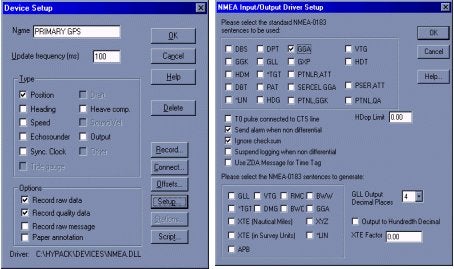
Figure 1: NMEA Device driver setup in Hardware
Now you can load the otfgyro.dll (listed as Coastal Oceanographics OTF-Gyro/Comparison) into the Hardware program. Choose otfgyro.dll from the device list. Hardware will only allow you to check the Heading box. Under the Setup button, be sure to check the message(s) coming in from the GPS (Figure 2). You can also set a distance alarm, which will notify you if the calculated distance between the two GPS antennas exceeds the theoretical distance as defined by the offsets entered in the Hardware program. You MUST enter your offsets in this driver. You should be as accurate as you can with these offsets, as this will be key in determining the correct heading.
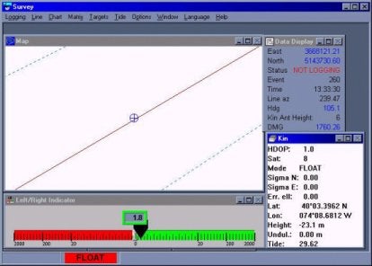
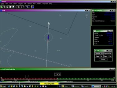
Your otfgyro setup is complete once you've connected the receivers to your com ports. Survey will now calculate heading based on position of two GPS antennas. Users can also view the OTF window in Survey (see Figure 3), which gives a visual heading representation, and also displays the distance between the two antennas. The Data Display will display heading, and also give you a distance error between the two antennas.
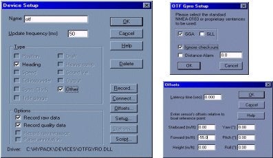
Figure 2: otfgyro Setup in Hardware
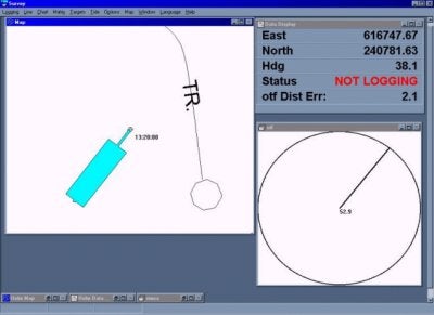
Figure 3: Survey Program
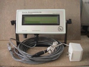
QSHD4-40操舵用ディスプレイ(SHD4-40 Helmsman Display)
FAQ ID:Q4-6
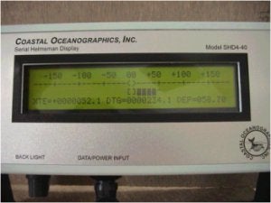
SHD4-40シリアル操舵手用ディスプレイは、操船や測線上を測量する時に操舵手へ必要な情報を供給する為に作られました。これは安価で小型、軽量、丈夫に作られているので小型船での測量にぴったりです。SHD4-40は、HYPACK® survey ソフトウェアと併せて使えるよう組み合せられています。電源とデータは1つのケーブル(4本の線を使用)で供給されるので、簡単かつ迅速に設置出来ます。情報は、工夫された4行×40文字のLEDバックライト付き液晶ディスプレイに表示されます。
操作は最小限に抑えられており、唯一の外部調整は、バックライト強度です。可動式のスタンドにより机上、壁、デッキヘッドへの設置を可能にし、たいていの現場 において艤装できます。値の文字表示に加えて、アナログ自動レンジ調整棒グラフ形式の左右操船指示機能も含まれております。完全防水では有りませんが、 雨、飛沫等のたいていの測量現場において経験する状況に対応できます。
仕様:
|
寸法: |
21cm x 13cm x 4.5cm |
|---|---|
|
ケース: |
Hammond ABS Flame Retardant |
|
電力: |
8VDC~15VDC @ 300mA (最大) |
|
データ入力: |
9600 / 19200 baud 8N1 |
|
電源/I/O ケーブル: |
標準0.5m(必要に応じて延長可) |
|
電源/データコネクタ: |
Switchcraft EN3 Weathertight |
|
ディスプレイモジュール: |
LEDバックライト付Seiko STN Yellow/Green |
|
ディスプレイ寸法: |
147 x 29.5 mm |
|
文字サイズ: |
2.78 x 4.27 mm |
|
ドットサイズ: |
0.55 x 0.55 mm |
|
フォーマット: |
40文字4 行 |
|
可動式のスタンド: |
360°回転可能 |
SHD4-40シリアル操舵手用ディスプレイに関する更なる情報は東陽テクニカ営業第3部までお問い合わせください。
Q千本電気社、カイジョー社製測深機の使用
FAQ ID:Q4-7
- 下表を参考にして適切なデバイスドライバ(xxx.DLL)をHYPACKハードウェア設定より選択します。
(注:下表に無いモデルはデータの取り込みが出来ませんので、東陽テクニカにご相談ください。) - 下表のフォーマットに合うように測深機の出力するデータフォーマットを測深機側にて調整します。
|
測深機 |
ドライバ |
データフォーマット(入力データ) |
読み込み水深値 |
|---|---|---|---|
|
PDR103 (千本電機) |
PDR130.DLL |
:HHMMSSYEDDDDD<CR><LF> (DDDDDの位置が水深データ) |
DDD.DD(例:DDDDDが01234の場合12.34) |
|
PDR601 (千本電機) |
PDR6011.DLL |
:YEHHMMSSLLLPPPDDDDD<CR><LF> (DDDDDの位置が水深データ) |
DDD.DD(例:DDDDDが01234の場合12.34) |
|
PDR601 (千本電機) |
PDR6014 .DLL |
:YEHHMMSSLLLPPPDDDDDFFFFFGGGGGJJJJJ<CR><LF> (DDDDDの位置が水深データF,G,Jも同様) |
4 個の水深値 ch1:DDD.DD(例:DDD.DDが01234の場合12.34) ch2:FFF.FF(例:FFF.FFが01234の場合12.34) ch3:GGG.GG(例:GGG.GGが01234の場合12.34) ch4:JJJ.JJ(例:JJJ.JJが01234の場合12.34) (4個の水深値を処理する為には、マルチビーム測深機対応のドングルが必要になります。) |
|
PS20R (カイジョー) |
PS20R.DLL |
データフォーマットの10番目から15番目に水深値が来るように設定してください。 |
123.45(水深値が12345で入力された場合) |
|
PS30R (カイジョー) |
PS30R.DLL |
????????DDDDD??SSTTTT |
DDD.DD(例:DDDDDが01234の場合12.34) |
QNMEA.DLLを使用してGPSから出力されるNMEA0183のメッセージ(GGA, PTNL_GGK等)をHypack Surveyプログラムで集録する
FAQ ID:Q4-8
QHypackから測深機のマーク信号をコントロール
- HYPACK用パソコンのHYPACKドングルにパラレル イベント ボックスのD-sub 25ピンオス型コネクタを接続します。 USBドングルを使用している場合はパソコンのパラレルポートにD-sub25ピンオス型コネクタを直接、接続します。なお、パラレルイベントボックスのD-sub 25ピンメス型コネクタは、プリンター等を接続する場合に使用します。
- このボックスには、9VDC角型電池(数週間の寿命)を使用しています。
ボックスを使用する時には、ボックスのスイッチを“ON”にして下さい。 - ボックスのBNCコネクタ(メス)と測深器のマーク信号入力コネクタ(千本電機社製 PDR1300測深機の場合、No,2”コネクタ(七星:NCS-163R))をケーブルで接続して下さい。
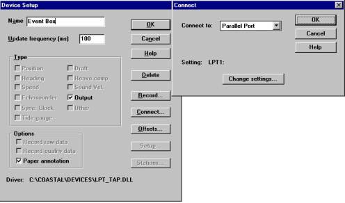
- HYPACK “Hardware”プログラムの“Devices”メニューの“Add Device…”で“Costal Oceanographics Event Mark Generator(LPT_TAP.DLL)”を選択し、以下の画面通りに設定を行なって下さい。
- 以上の設定を行ったら、SURVEYプログラム起動中にCtrl-Nキーを押下するか、LOGGINGメニューのMark eventをクリックすることで測深器にマーク信号を送信することができます。
QHypackで使用するGPSについて(Why should I use a fast update rate for a GPS that only updates 1Hz?)
FAQ ID:Q4-10
GPSデバイスのセットアップの際に"sync clock"オプションを設定すると、SurveyプログラムではGPSから送られてくるGGAメッセージのタイムタグを使用します。 しかしながら、他のNMEAメッセージにはタイムタグは含まれていません。 もし、非常に遅いアップデートレートを設定している場合、次のメッセージが流れてくるまでメッセージはコンピュータのバッファにとどまります。
以下の2つのグラフはアップデートタイムの異なる2つのGPSのポジションレコード(GGA)の時刻とヘディングレコード(VTG)の時刻の関係を示します。
VTGレコードにタイムタグは含まれていないためHypackではVTGレコードの解析にはコンピュータの時刻を使用するため以下のようなグラフとなります。
QRTK-GPSを使用し水位データ取得をするキネマティックドライバ(New Kinematic Driver for HYPACK® Max)
FAQ ID:Q4-11
HYPACK® Maxにあらたなデバイスドライバが追加されました。新しいドライバは、KINEMATIC.DLLです。これのドライバは、これまでのKIN.DLLとTRIMKIN.DLLにおき変わるもので、リアルタイムに潮位を得るために使用されます。
使用方法は、Hardware - Devices - Add Deviceで "Kinematic GPS (Real- Time- Tides) を選択します。
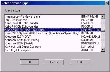
Figure 1
セットアップ方法は今までのドライバと同じです。(詳細は説明書を参照してください。)唯一の違いは、NMEAスタンダードキネマティックGPSとの互換性のためにNMEA-GGKのチェックボックスが追加されたことです。
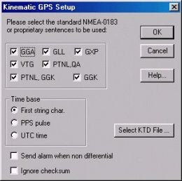
Figure 2
Q各センサーオフセット入力の詳細(Hardware Offsets and Origins)[英語]
FAQ ID:*Q4-12
We often get questions from users who are configuring their hardware and are getting lost in the maze of variables to consider in determining the origin, and changing offset signs. The key below is written to help guide you with these questions. Here's how it works.
Choose the first outline level that fits your setup. Now, under that heading, choose the second level heading that describes your setup. Continue progressing down through the headings until a setup table follows your last choice.
The setup table tells you what to use for the origin, which Hardware program each device should be entered in, and the signs used for the offset measurements.
Note: In all setups, except for the GPS, latency is usually zero. You may enter a value initially from the GPS manual or start with it at zero, but you should run a Patch Test and adjust this setting accordingly. Sonar systems usually automatically compensate for latency. Latency is not an issue for MRUs and Gyros.
I. Single Vessel
A. Gyro for heading
1. Single Beam
| Consideration | Solution |
|---|---|
| Origin |
Transducer
|
|
Hardware Setup Program(s)
|
Hypack Hardware- All devices
|
| Offset Signs & Program(s) |
Horizontal offsetsare positive forward and starboard Z offsets: Transducer: 0--included in draft correction of device when calibrated GPS: Positive upward |
2. Multibeam
There are two possible options for setting up multibeam systems. Solution A maintains the origin always at the vessel's pivot point. Solution B uses the transducer head as the origin in Hypack®Hardware, while Hysweep®Hardware uses the vessel's pivot point. In this case, the helmsman display data is based on the transducer, enabling more accurate positioning of the transducer over the survey line.
Note also, in most cases, the rotational offsets of the gyro and MRU are calibrated during installation to the vessel. Any additional error will be compensated for by the Patch Test values that are then applied to the transducer.
| Consideration | Solution A |
|---|---|
| Origin |
|
| Hardware Setup Program(s) |
Hysweep Hardware-MRU, Transducer, Gyro, Hypack.dll |
| Offset Signs & program(s) |
Horizontal offsets: positive forward and starboard of the origin. Z offsets: Transducer: 0--included in draft correction of device when calibrated. GPS: Positive upward from the waterline in Hypack®Hardware; positive downward in Hysweep®Hardware. MRU: For MRUs use zero.** Yaw Offset: Transducer (Determined in Patch Test.): positive for clockwise rotation from alignment with the keel. Gyro*: Usually zero. May add correction for variation between magnetic N and true N. Add the variation to the mounting offset using positive values for clockwise rotation from alignment with the keel. MRU*: positive for clockwise rotation from alignment with the keel. Pitch offset (Determined in Patch Test.): Multibeam sensors not oriented directly below the vessel. Positive forward. Roll offset (Determined in Patch Test.): Multibeam sensors and MRUs* not oriented directly below the vessel. The reference roll angle (in decimal degrees) is 0 for vertical mounting positive to the port side. |
| Additional settings |
If MRU is not at the vessel pivot point, when you edit your data, check Correct for Induced Heave in the Advanced Read Parameters dialog.
|
| Consideration | Solution B |
|---|---|
| Origin |
Hypack Hardware: Transducer
Hysweep Hardware: Vessel pivot point-ideal MRU position |
| Hardware Setup Program(s) |
Hypack Hardware-GPS, Hysweep.dll (optional)
Hysweep Hardware-Transducer, MRU, Gyro, Hypack.dll |
| Offset Signs and program(s) |
Horizontal offsets: positive forward and starboard of the origin. Z offsets: GPS: Positive upward from the waterline in Hypack®Hardware, positive downward in Hysweep®Hardware. Transducer: 0--included in draft correction of device when calibrated. MRUs use zero**. Yaw Offsets: Transducer (Determined in Patch Test.): positive for clockwise rotation from alignment with the keel. Gyro*: Usually zero. May add correction for variation between magnetic N and true N. Add the variation to the mounting offset using positive values for clockwise rotation from alignment with the keel. MRU*: positive for clockwise rotation from alignment with the keel. Pitch offset: For multibeam sensors (determined in Patch Test.) and MRUs* not oriented directly below the vessel. Values are positive forward. Roll offset: Multibeam sensors (determined in Patch Test) and MRUs* not oriented directly below the vessel. The reference roll angle (in decimal degrees) is 0 for vertical mounting. Values are positive to the port side. |
| Additional settings |
If the MRU is not at the vessel pivot point, when you edit your data, check Correct for Induced Heave in the Advanced Read Parameters dialog of the editor.
|
3. Multiple Transducer
a) System supported in Hypack Hardware.
| Consideration | Solution |
|---|---|
| Origin |
Vessel pivot point-ideal MRU position
|
| Hardware Setup Program(s) |
Hypack Hardware-all devices
|
| Offset Signs & program(s) |
Multitransducer offsets are entered in the Transducer Offsets Program. Horizontal offsets: positive forward and starboard of the origin. Z offsets: GPS & Transducer: positive upward from the waterline. MRU: Use zero.** Yaw Offset Gyro*: Usually zero. May add correction for variation between magnetic N and true N. Add the variation to the mounting offset using positive values for clockwise rotation from alignment with the keel. |
b) System supported in Hysweep Hardware
| Consideration | Solution |
|---|---|
| Origin |
Vessel pivot point-ideal MRU position
|
| Hardware Setup Program(s) |
Hypack®Hardware: GPS, Hysweep.dll (optional)
Hysweep®Hardware: Transducers, Gyro, MRU, Hypack.dll |
| Offset Signs & program(s) |
Hypack®Hardware:
Horizontal offsets: positive forward and starboard of the origin. Z offsets: GPS: positive upward from the waterline. Hysweep®Hardware:·Horizontal offsets: positive forward and starboard of the origin. Z offsets: GPS in Hypack.dll is positive downward. Transducer: positive downward from the waterline. MRU: Use zero.** Yaw Offset: Gyro*: Usually zero. May add correction for variation between magnetic N and true N. Add the variation to the mounting offset using positive values for clockwise rotation from alignment with the keel. |
4. Single Beam and Multibeam
| Consideration | Solution |
|---|---|
| Origin |
Hypack®Hardware: Transducer most important over survey line.
Hysweep®Hardware: vessel pivot point |
| Hardware Setup Program(s) |
Hypack®Hardware: GPS, Single beam Transducer, Hysweep.dll (required--passes heading to Hypack®Survey)
Hysweep®Hardware: Multibeam Transducer, MRU, Gyro, Hypack.dll (passes position to Hysweep®Survey) |
| Offset Signs and program(s) |
Hypack®Hardware:
Horizontal offsets: positive forward and starboard of the origin. Z offsets: Positive upward from the waterline. Hysweep®Hardware: Horizontal offsets: positive forward and starboard of the origin. Z-offsets: GPS in Hypack.dll is positive downward. Transducer: 0--included in draft correction of device when calibrated. MRU: Use zero.** Yaw Offsets: Transducer (determined in Patch Test) & MRU*: positive for clockwise rotation from alignment with the keel. Gyro*: Usually zero. May add correction for variation between magnetic N and true N. Add the variation to the mounting offset using positive values for clockwise rotation from alignment with the keel. Pitch offset: Multibeam sensors (Determined in Patch Test) and MRUs* not oriented directly below the vessel. Positive forward. Roll offset: Multibeam sensors (determined in Patch Test) and MRUs* not oriented directly below the vessel. The reference roll angle (in decimal degrees) is 0 for vertical mounting-use values positive to the port side. |
| Additional settings |
If MRU is not at the vessel pivot point, when you edit your data, check Correct for Induced Heave in the Advanced Read Parameters dialog.
|
5. 2 Single Beam Systems
| Consideration | Solution |
|---|---|
| Origin |
The transducer that is most important to keep over your survey line.
|
| Hardware Setup Program(s) |
Hypack Hardware- All devices
|
| Offset Signs & program(s) |
Horizontal offsets are positive forward and starboard Z offsets: Transducer: 0--included in draft correction of device when calibrated GPS: Positive upward |
B. GPS for heading (1or 2)
If you are using 2 GPS and OTFGYRO.dll, the forward GPS is the origin and is the only one where latency offsets should be applied.
1. Single Beam
| Consideration | Solution |
|---|---|
| Origin |
GPS
|
| Hardware Setup Program(s) |
Hypack Hardware- All devices
|
| Offset Signs & program(s) |
Horizontal offsets are positive forward and starboard Z offsets: Transducer: 0--included in draft correction of device when calibrated GPS: Positive upward |
2. Multibeam -- not recommended
3. Multi-transducer
The origin is at the GPS. All else is the same as multitransducer systems with a Gyro.
4. Single beam and Multibeam-not recommended
5. 2 Single beam
The origin is at the GPS. All else is the same as multitransducer systems with a Gyro.
II. Multiple Vessels
A. Towfish
Towfish Offsets and Measurements
Offsets for any devices on the vessel are measured from the vessel origin.
The cablecnt.dll and towcable.dll in Hypack®Hardware uses the towfish depth, Z?offset and corrected cable length to calculate the horizontal distance from the A?frame connection point to the towfish. That distance is added to the Y?offset to calculate the layback.
Offsets on the Towfish are from the connection point of the cable to the towfish. The hopper arms on a dredge are also configured with reversed horizontal offsets and from the connection point of the arm.
Note: When configuring offsets for the cablecnt.dll or towcable.dll, and the Towfish or other Mobiles in the Hypack®Hardware program, regardless of what type of mobile you have, port and starboard offsets specified in the Offsets dialog must have their signs reversed from the way you normally express offsets for other devices.
| Measurements | Normal Device Offsets | Mobile Offsets |
|---|---|---|
| Port and Aft | Negative | Positive |
| Starboard and Forward | Positive | Negative |
The example below illustrates a towfish setup
| Towfish with Simple Layback | |||
|---|---|---|---|
 |
Devices | Dialogs | |
| Driver Setup | Offsets | ||
| GPS | Starboard -5
Forward -5 Height antenna height (not shown) |
||
| Cablecnt.dll or Towcable.dll | Y Offset -20
Z Offset=height above water (not shown) |
Starboard -5
Forward 0 Height 0 |
|
| Towfish Device | Starboard 0
Forward -10 |
||
| Cable out is controlled in the Survey program. | |||
Note: In this example, it is also correct to use the following settings for the Cablecnt.dll or Towcable.dll.
| Devices | Driver Setup | Offsets |
|---|---|---|
| Cablecnt.dll or Towcable.dll | Y Offset 0
Z Offset = height above water (not shown) |
Starboard -5
Forward 20 Height 0 |
The Track point systems calculate the towfish position. No towfish offsets or cable out distances are required.
| Track Point Systems | |||
|---|---|---|---|
 |
Devices | Dialogs Offsets | |
| GPS | Starboard -5
Forward -5 Height antenna height (not shown) |
||
| Track point | Starboard -10
Forward 20 Height 0 |
||
| Dredge Systems | |||
|---|---|---|---|
 |
Devices | Dialogs Offsets | |
| Hopper Arm #1 | Starboard 12
Forward -10 |
||
| Hopper Arm #2 | Starboard -4
Forward 10 |
||
B. Independent Multiple Vessels
A central vessel can track multiple vessels via radio modems. Set up the devices on each vessel individually. The NMEA.dll can be setup to output GGA, VTG and DBT messages via the radio modem to the data collection vessel. You can also use the Shared Memory NMEAOUTPUT program to send the desired data to the collection vessel. If you will be tracking more than one vessel in this manner, the radio modems must be of different frequencies so that the collecting computer can differentiate between devices.
The data collection vessel will have a NMEA.dll configured for each incoming message to receive the data and record data from each sensor separately. The survey screen on the collection vessel can display all of the vessels from which it is receiving data.
Q各センサーのオフセット入力(Position Offsets in Hysweep Hardware)
FAQ ID:Q4-13
HypackHardwareプログラムで入力されるオフセット値はSurveyプログラムで表示されるときに反映されるのみで、データの補正には 使用されません。マルチビームデータにポジションのオフセットデータを反映するにはHysweepHardwareに入力します。
上図では各オフセットの原点はソナーヘッドとなっています。Surveyプログラムの下部に表示されるHelmsmanディスプレイに表示される値はこの原点を使用します。
Hysweepプログラムでは通常動揺中心(通常モーションセンサーが設置されるところ)を基準にします。この際Hysweepプログラムで入力されたポジションオフセットはデータに反映されます。
Qマルチビームのロールオフセット値の影響(Multibeam Roll Offset Effects)
FAQ ID:Q4-14
以下にロールオフセットに関する問題について記述しましたので参考にして下さい。
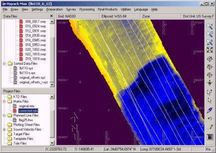
下図は5×5のマトリックス画面です。黒ずんだ部分に注意してください。黒ずんだ部分がうまく整合していないことがわかると思います。これは典型的なロールオフセットミスが原因となって発生する現象です。

他の設定は全て変更せずに、パッチテストの結果を適用すると下図のように黒ずんだ部分の不整合性がみごとに解消されます。この例の場合は水深約45 フィート、ロールオフセット1.75°でした。この測深機の場合、水深約45フィートでロールが1.75°ずれた場合の海底における位置誤差は水平位置で 1.4フィート、水深で1.44フィートです。
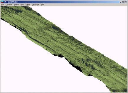
この問題はTinモデルプログラムを使用するとより確認しやすくなります。下図はロールオフセットを補正する前のTinモデルです。測線に沿って筋が出現していることが確認できます。
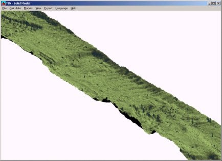
下図は補正後のTinモデルです。上図で出現しているロールオフセットエラーによる筋が消滅していることが確認できます。
Qネットワークインターフェースを使用するドライバ(SeaBat81XX)について(HYSWEEP® Network Drivers)
FAQ ID:Q4-15
以下の機器がネットワーク接続にて使用できます。
- Atlas Fansweep 20
- Reson Seabat 8124 and 8125
- Simrad EM3000
これらのドライバでは高速なデータ転送をサポートします。
Reson社のSeaBat8125は240本のビームを最大40Hzで音波を発信します。つまり1秒間にトータル9600の測深データがえられます。時間あたりに換算すると34,560,000の測深データとなります。
故にシリアルポートよりも高速なネットワークを使用してデータ収録を行う必要があるわけです。
以下のリストはHYSWEEPで使用できるドライバです。
| Driver | Description |
|---|---|
| Atlas Bomasweep | Multiple transducer driver |
| Atlas Fansweep (Network) | Multibeam driver using the network interface |
| Atlas Fansweep (Serial) | Multibeam driver using the COM port interface |
| HYPACK® 8.9 | Link to HYPACK® survey |
| HYPACK® Max | Link to HYPACK® survey |
| KVH Gyrotrac | Heading, pitch and roll driver |
| NMEA-0183 Gyro | Gyro driver for NMEA HDT messages |
| Odom Echoscan II | Multibeam driver |
| Odom Miniscan | Multiple transducer driver |
| Reson Seabat 8101 | Multibeam driver |
| Reson Seabat 81xx (Network) | 8124, 8125 and newer 8101 multibeam driver using the network interface |
| Reson Seabat 81xx (Serial) | 8124, 8125 and newer 8101 multibeam driver using the COM port interface |
| Reson Seabat 9001 | Multibeam driver |
| Reson Seabat 9003 | Multibeam driver |
| Seabeam SB1185 | Multibeam driver |
| Seatex MRU6 | Heave, pitch and roll driver |
| SG Brown 1000S Gyro | Gyro driver |
| Simrad EM3000 | Multibeam driver using the network interface |
| Simrad SM2000 | Multibeam driver |
| TSS 335B | Heave, pitch and roll driver |
| TSS DMS | Heave, pitch and roll driver |
| TSS Pos/MV | Heave, pitch and roll driver |
SeaBat8125からネットワーク経由で出力されるデータをHYPACKMAX00.5aを使用して集録するための 手順を示します。
手順としては、次の4項目があります。
- SeaBat8125プロセッサーとHYPACKMAXパソコン間の接続。
- HYPACKMAXパソコンの「コントロール パネル」>「ネットワーク」設定。
- HYPACKMAXのHysweep Hardwareプログラムでの設定。
- SeaBat8125プロセッサーのメニュー設定。
これらの項目について次に示します。
1.SeaBat8125プロセッサーとHYPACKMAXパソコン間の接続
プロセッサー背面に有ります「10BASE-T」と「PORT 1」を次のように接続します。
1)「10BASE-T」とHYPACKMAXパソコンのネットワーク端子間をEthernetクロス ケーブル(RJ45コネクタ)で接続します。
2)「PORT 1」とHYPACKMAXパソコンのRS-232C COMポート(例:Com1)間を クロス(リバース)ケーブルで接続します。
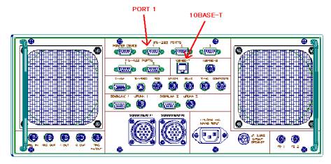
図1.SeaBat8125プロセッサーの背面
2.HYPACKMAXパソコンの「コントロール パネル」>「ネットワーク」設定
ここでは、プロセッサーのBITE画面内に表示されています「Remote:」アドレスと 「Subnet:」マスクをHYPACKパソコンの「コントロール パネル」>「ネットワーク」 アイコンで設定します。
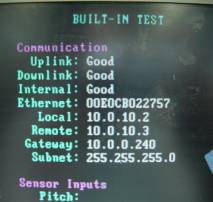
図2.SeaBat8125のBITE画面
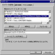
図3.Windowsネットワーク画面
ご使用されていますネットワークカードのTCP/IPコンポーネントを選択しプロパティ ボタンを押すと図4のような画面が表示されます。
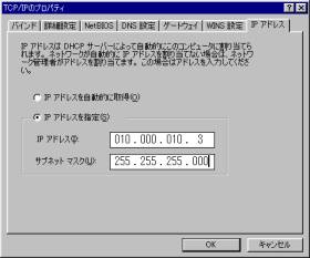
図4.TCP/IPのプロパティ画面
このTCP/IPのプロパティ画面でIPアドレスの指定を行ないます。(図2,4参照)
ここで、IPアドレスの指定を行なった後に画面にしたがって「OK」ボタンを 押していくとWindowsが再起動されます。
3.HYPACKMAXのHysweep Hardwareプログラムでの設定
Hysweep Hardwareプログラムにて、図5のようにRESON SeaBat 81xx(Network) ドライバの設定を行ないます。
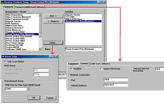
図5.Hysweep Hardwareプログラムでの設定
1)「Equipment」タブ内で「Manufacture/Mode」リストからRESON SeaBat81xx(Network)を 選択してAdd→ボタンを押します。
2)「Installed」リスト内のRESON SeaBat81xx(Network)を選択した状態でSetup…ボタン を押すとRESON Setup画面が表示されます。
ここで、SeaBat8125がサイドスキャン・オプション付きでサイドスキャンデータを 集録する時には、「Side Scan Option」チェックボタンにチェックを付けて下さい。
また、「81xx Network Driver」項目では、SeaBatプロセッサー背面のPort 1と 接続されるパソコンのCOMポートを選択します。
これは、ネットワーク接続によってデータ集録するために必要な時間データをパソコン からプロセッサーに送信するためです。
3)「Connect」タブ内の「Enabled」チェックボタンにチェックを付けます。
そして「Network Connection」項目で、Portを1028に設定しInternet Addressには、 プロセッサーのBITE画面の「Local:」アドレスを設定します。(図2参照)
4.SeaBat8125プロセッサーのメニュー設定
ここではSeaBatのデータをネットワークで出力させるための設定とサイドスキャンデータ 出力のON/OFFについて示します。
これらの設定は、BITE画面内に有るメニューから行ないます。
データをネットワークで出力するために...(図6参照)
(ア)「MENU: Config」メニューの「Output:」項目をETHERNETに設定します。
(イ)同メニューの「UDP Base:」項目を1028に設定します。
(ウ)同メニューの「TimeBd:」項目を9600に設定します。
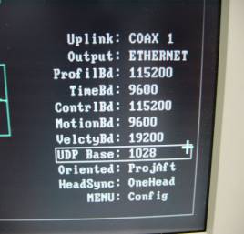
図6.BITE画面内の「MENU: Config」
サイドスキャンデータ出力のON/OFF...(図7参照)
「MENU: Modes」メニューの「Sidescan:」項目をRMSに設定します。
また、出力をOFFにする時には同項目をOFFに設定して下さい。
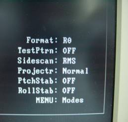
図7.BITE画面内の「MENU: Modes」
QHysweepHardwareプログラムへのヘディングセンサーデータの入力(Generic Attitude Driver)
FAQ ID:Q4-16
一人のHYPACK® ユーザがつい最近ヘディングデバイスよりマルチビーム測深機の為に直接Hysweep® Surveyへデータを入力することを望んでいました。HYPACK® Hardwareにおいてはこの事は可能でしたがHysweep® Hardwareでは、できませんでした。
ユーザがヘディングデバイスから出力されるデータを我々に供給してくれたので、Hysweep® Hardware での設定は非常に簡単でした。以下にどのように設定したのか示します。
一度Hysweep® Hardwareプログラムを開き(Preparation - Hysweep® Hardware メニュー) デバイスリストよりGeneric Attitudeを選択しAddをクリックします。次にSetupボタンをクリックします。ここがデバイスのデータの情報を入力する場所です。ここでのデバイスはヘディングデバイスであり下記のようなデータを出力します。
$GPGGA,063442.6,3540.890,N,13946.506,E,9,6,2,35,M,74,M
$GPVTG,295.9,T,,,0.08,N,,
$PSER,ATT,063442.800,20,05,1999,+295.50,T,-00.16,-02.30,02.8,06>05,035,0
$A,0.1,+295.50,T,-00.16,-02.26,0
$A,0.2,+295.51,T,-00.17,-02.22,0
$A,0.3,+295.51,T,-00.17,-02.18,0
$A,0.4,+295.51,T,-00.18,-02.14,0
このメッセージの中には別のデータがふくまれており、これは、デバイスが$GPGGA よりの測位データや$GPVTGよりの船速及びヘディングデータもまた出力していることを示します。この場合は、$Aの列のヘディングデータを必要としていました。簡単に下記に示すように情報を入力して下さい。
ヘディングの為のデータを使いたいので、Heading 項目をチェックしてください。
次のステップは、Synchronization項目に情報を入力します。複数のデータ列がありますが、$Aの列のみを使いたいので、Start of Lineボックスをチェックし、はじめの数文字をStart Character Sequence項目に入力します。この場合、他の列ではなく、$A 列のみを使用する事をドライバに知らせる為"$A,"を入力します。続いて、この列がキャリッジリターン/ラインフィードで終わるので、End of Line <CR><LF> ボックスをチェックします。
次に、このドライバのParsing areaに行きます。この列は、カンマにより範囲を決められていますので、Comma Separated Fields項目をチェックしmultiplier (倍率器)を1.0に設定します。ここで、どこのフィールドがヘディング情報を含んでいるかを指示できます。下記のようなデータ列を考えているならば:
$A,0.1,+295.50,T,-00.16,-02.26,0
カンマで区切られた3番目の部分を使用したいので、ここで3をHeading項目に入力します。
全ての項目を正しく入力しOKをクリックします。そして、正しいポートに接続しオフセットを入力します。
これで、Hysweep® Surveyプログラムを使用して正確にヘディングデータを収録できます。また、hysweep.dll (Coastal Oceanographics Hysweep® Interface)をHYPACK® Hardwareに追加することにより、 HYPACK® Surveyへデータを送ることができます。HYPACK® Surveyはシェアードメモリ経由でHysweep® Surveyからデータを受信できます。
Q室内シュミュレーション用ドライバ(Sim32.dll)
FAQ ID:Q4-17
Sim32.dllオフィス内でシュミュレーションを行うために作成されたドライバです。このデバイスではポジション、深度、方位をシュミュレーションすることができます。
Simulation Setup
SimulationはHypackHardwareプログラムでセットアップします。
- DEVICES-ADD DEVICEでSim32.dll (Coastal Oceanographics' Generic Simulator)ドライバを選択します。
- 実際にシュミュレートされているか確認してください。
- [Setup]ボタンをクリックし、初期設定を行います。
| ボートの設定 |
初期 X, Y, 初期方位 (in degrees), 船速 (in knots) を設定します。 ヘディングセンサーのオフセットはボートの座標軸が初期方位と異なっている場合に入力します。 Speed Incrementはマウスで1クリックしたときに上昇する速度を入力します。 |
|---|---|
| 機器の設定 |
Sim32.dllドライバでは様々な測深器をシュミュレートします。
シングルビーム マルチビームまたはマルチトランスデューサー |
| シュミュレーションの設定 |
ポジションに関してはファイルから読み込むか、ドライバが生成するデータを利用するか選択可能です。
Positions from data files: Program-generated positions: |
Running your Simulation
Sim32.dllの設定が終了するとSurveyプログラムでシュミュレートが可能となります。
Surveyプログラムを起動するとシュミュレータのコントロールウィンドウが表示されます。このウィンドウを操作することで、各デバイスのシュミュレートが可能となります。
QキネマティックGPS用ドライバ(Updated Kinematic.dll)[英語]
FAQ ID:Q4-18S
The kinematic.dll has recently been updated with added flexibility to accommodate more GPS messages. The user now has a choice of warning lights in the Survey program based on the GPS quality indicator within the data string. This modification was a necessity, due to the update of the NMEA 0183 standards (Version 3.0), and also for the GPS manufacturers that don't comply with the NMEA standards (Yep, we know who you are!).
The GPS quality indicator warns the user that they have dropped out of a mode, such as differential or kinematic, and is used in Hypack®'s NMEA-0183 (nmea.dll) and Kinematic GPS (Real-Time-Tides) (kinematic.dll) device drivers. This would result in a loss of position accuracy and, in the case of the kinematic driver, would also result in a loss of horizontal accuracy. Because the Kinematic driver is used to record water levels in real time, the recorded tide value in non-kinematic mode would end up being...well...junk.
These are the NMEA GPS quality indicators in a GGA string:
0 = Fix not available or invalid
1 = GPS SPS Mode, fix valid
2 = Differential GPS, SPS Mode, fix valid
3 = GPS PPS Mode, fix valid
4 = Real Time Kinematic. System used in RTK mode with fixed integers
5 = Float RTK. Satellite system used in RTK mode, floating integers
6 = Estimated (dead reckoning) Mode
7 = Manual Input Mode
8 = Simulator Mode
The previous kinematic driver had a quality indicator hard coded within the driver. The value of 3 was considered kinematic, so if the GPS output any other value other than 3, you would get a warning light in the Survey program. This worked for most GPSs, but not all.
The Setup dialog in the kinematic.dll now allows the user to change the quality indicator (see figure below).
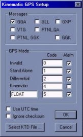
The user simply checks the alarm they would like to see in the Survey program. There is also a user-defined field, so you can choose the number code and the alarm message (see below).
The GPS Mode, number of satellites, HDOP, and antenna height are also output to the shared memory area while running in Survey.
QSeismic gun用CSRShotドライバについて(CSRShot.dll)[英語]
FAQ ID:Q4-19
The CSRShot.dll is used to trigger seismic guns at pre-determined intervals along the planned survey line. It sends a message out a serial port to your equipment at a regular, user-defined distance interval along your planned survey line (not the trackline).
At each occurrence, you may choose to:
- Store the position and time data to your raw survey file.
- Trigger the seismic guns, annotate your echosounder and send data to the CSRShot device window in Survey.
Version Number
01.01
Device Setup
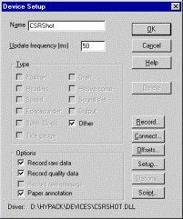
There are two key settings in the device setup dialog:
- Other records position, depth and time to your survey data file and tags the data with "SPO". (See Output Strings.)
- Paper Annotation triggers the seismic guns, marks this occurrence on the echosounder and displays the data in the CSRShot device window in Survey.
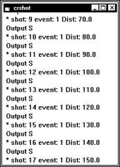
A Sample CSRShot Device Window in Survey
Driver Setup
The CSRShot Driver Setup Dialog
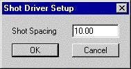
The driver setup simply defines the distance you wish between events. It must be a positive value and is measured in survey units according to your geodetic parameters.
It is important to remember that the distance is measured in even increments down the planned survey line not the length of the trackline. For example, if the shot spacing is 10 survey units, no matter how well (or poorly) the helmsman steers the vessel down the survey line, the event marks will still only be generated when it passes points that are calculated at 10, 20, 30, etc survey units down the survey line.
Connection Setup
Specify the serial port where the "S" message is to be transmitted to trigger the seismic guns.
Output String
| Survey Status Codes | |
|---|---|
| 0 | Automatic Event Basis set in Navigation Parameters |
| 1 | Manual Event Basis set in Navigation Parameters |
| 3 | Manual Event created. |
Special Notes
- Deselecting the Paper Annotation option also discontinues shot generation. Since this is the purpose of the driver, it disables the driver.
- This works differently than the echosounder device drivers Event Interval option in Survey's Navigation Parameters, which is based on the trackline.
- A Planned Line file, using only single segment lines, must be enabled in your Survey design because the output is based on the measured distance from the beginning of the line.
- You cannot end and restart logging mid-way down a survey line and always expect the driver to continue generating events. You can, suspend and resume logging without interrupting the shots.
- You must navigate your vessel in the direction of the survey line. (The circle indicates the starting end of the survey line.) If your vessel is at the wrong end of the line, use Survey's Swap Line feature to reverse the line direction.
Qイーサネットを利用したGPSデータの取り込み(Network monitoring of vessel position using NetNMEA driver)[英語]
FAQ ID:Q4-20
The latest addition to the list of device drivers is the NetNMEA driver. This is a network ready driver that uses the UDP protocol to receive NMEA messages in a network environment. In conjunction with the NetNMEA driver a change has been made to the NMEA Output program in HYPACK Max to allow the NMEA Output program to send the NMEA messages to a UDP port. The following instructions explain the method used to configure both the sending and receiving of NMEA messages over the network.
Before we begin the actual steps of installing the device and configuring the port a little background information about IP addresses and Ports. Every computer on a network has an IP address. This is a series of 4 numbers that are individual to the computer. These numbers can either be assigned by a server dynamically or specified in the computer statically. In this explanation the IP addresses are going to be static. Most applications of the NetNMEA driver are going to be with static IP addresses. No two computers can have the same IP address or the computers would not know when to respond to a request. A typical IP address would be 192.168.1.2. This is the address of the Server at Coastal Oceanographics Inc. To see another computer on the network the computers must have IP addresses on the same sub-net. This brings us to the other half of an IP address. The Sub-Net. A sub-net is another series of 4 numbers that help define the network. In this application for the computers to see each other the sub-net must be the same. Now a bit about ports. Every computer has certain ports set aside for particular functions. Port 21 for example is the standard FTP port of the computer. Port 80 is the port used to access Web Pages on the computer. Ports are similar to windows. To hear what the neighbor is telling you, you have to be at the right window. Generally pick a port that is not used by the computer for something else. I used port 6650.
Now that the boring network stuff is done we can begin the actual setup of the computer to use this. To add the NetNMEA driver to the Hardware configuration start Hardware as you normally would and select Devices -> Add Device. The NetNMEA is listed in the device listing as NMEA-UDP just below NMEA-0183. Add this device to your setup. The configuration of the NetNMEA is similar to the NMEA driver.
The options for the NetNEMA driver are the same. I have chosen just position, speed and heading here. If I were setting this up to monitor another vessel the Echosounder option would most likely be checked as the NMEA Output program can convert the depth from the other vessel into a NMEA depth string independent of the type of Echosounder that is actually used.
The biggest difference between the NetNMEA driver and the standard NMEA driver is the Connect option. The NetNMEA driver uses the Connect to: Network option. Select the Change settings button to specify the port. The Hardware program was originally designed to have an IP address, Port and Computer Name for the remote computer. The only item that is required is the Port.
Remember from the boring network section that a port must be chosen to allow the data a window to pass through to us. This is all that is required to receive NMEA over the network.
To configure the NMEA Output program Select the Connect option and Choose network. It is critical that the sender, NMEA Output program know who is being sent the message. The NMEA Output program requires an IP address to send the message to. This doesn’t mean that if you don’t know the address of the receiving computer that you cannot send messages. Lets look at an example.
There are two dredges that are running in a Construction project. They are connected via a high speed wireless network. The dredge company decides to show both vessels on the screen in both dredges. This is our sample project. ( Yes, this is being done.)
Both dredges have GPS, Gyro and Depth. To configure the dredge with the ability to see the other dredge the NetNMEA driver must be added to the Hardware configuration of both dredges. The port must be different for each pair of connectors. Dredge 1 NetNMEA receives data from Dredge 2 NMEA Output program. They should have the same port specified as should the other pair. This device is added to another mobile in the hardware configuration. When the Survey program is run the user must start the NMEA Output program in Survey under Options -> Shared Memory so that data is sent to the other dredge. Once the program is running and the appropriate messages are selected the user starts sending data and the other dredge should be able to see the mobile on screen. If depth is desired for the other dredge send the DBT message and configure the receiving dredge with that message.
Just a quick note about sending messages. If it is desired to send the data to more than one other computer the message can be broadcast. This is also useful if the IP address of the target computer is unknown. In the NMEA Output program send the data to the IP address on the network ending in 255. In Coastal we would send the data to 192.168.1.255. This broadcasts the message.