FAQ
HYPACKに関する質問
2.測量準備と補正(Preparation & Calibration)
ID.Q2-8
Q. 水路設計(チャンネルデザイン)プログラムにおける急な変化を含むトウラインの処理(Channel Design with Sharp Turns in the Toe Lines)[英語]
A.

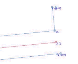
A client recently had trouble creating an LNW file using the CHANNEL DESIGN program. The problem end of the channel is shown in the figure to the right.
The Left Toe line is shown at the top of the figure in blue, with points 2L, 3L and 4L being visible. There is a 90º turn at each point.

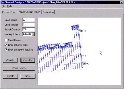
When the planned lines were generated in the CHANNEL DESIGN program, the result is shown in the figure right.
At first glance, it appears that lines 8+80, 9+00 and 9+20 have been extended too far from the left toe line and are erroneous.

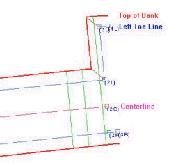
It turns out the CHANNEL DESIGN is doing a pretty good job in this case! Take a look at the figure to the right.
One of the first things that CHANNEL DESIGN does is to construct the Left and Right "Top of Bank" lines. These are constructed from the positions of the toe lines and the side slope information. The Left Top of Bank line is shown in red at the top of the figure.
CHANNEL DESIGN is smart enough to be able to handle the 90º turns and generate the correct top of bank line.
For each planned line, the program then checks to see where it crosses the "toe line" and where it crosses the "top of bank" line.
As a test, I changed the Side Slope on the left side of the channel from "2" to "0.5". This would result in a "steeper" bank and the Top of Bank line should be generated closer to the Left Toe Line, eliminating the "long" lines at the end of the channel.
The figure to the right shows the result, confirming the fact that CHANNEL DESIGN is working as designed in this case.