HYPACKに関する質問
17.曳航体、ROV(Towfish - ROV)に関するFAQ
QROVが操作エリアに存在するか確認する
ROVのオペレーションのために新しいデバイスドライバを作成されました。ドライバの目的は、ROVがいつそのオペレーティング限界に達したかをオペレーターに通知することによってROVの安全なオペレーションを維持することです。
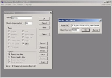
オペレータは、ドライバを利用するために、最初にHypackでBorderファイルを作成しなければなり ません。Borderファイルを作成しているとき、最後のポイントは、エリアの中または外で右クリックをします。この操作によって境界を閉じることができ ます。右クリックのロケーションは、ROVがその境界のどちらに存在するかによって決められます。あなたが境界の中でクリックするならば、ROVは、境界 内をオペレーションエリアとして扱います。そのドライバは、境界をオペレーションエリアとしても排他エリアとしても扱うことが出来ます。下記は、 Hardwareプログラムのセットアップの例です。
次のイメージは、Surveyプログラム上でバージニアビーチ沖のオペレーションエリアに入る軍艦を示しています。これは、港からオペレーションエリアの外へ出ることの計画トラックを用いて作成されたシミュレーションです。
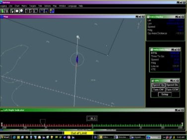
上のイメージにおいて、船は、境界線の外にあり、アラームが表示されている。
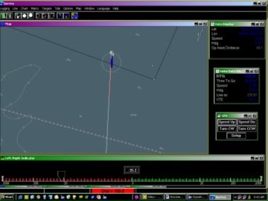
このイメージにおいて、船は、100フィートのアラームリミット内に存在する。
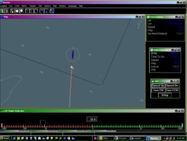
最終的に、船は、オペレーションエリアの内側にあり、オペレーションエリアの端への距離がData Displayにリストされることに注目してください。船の周りに、ビジュアルバッファアラームとして500フィートのサークルが表示されます。同じく船には、意図した動きのために10秒ベクトルが表示されます。
Q曳航体用ケーブルの使用(Using a Towfish with the Cable Counter)[英語]
FAQ ID:Q17-2
This note briefly describes how to use the cable counter driver to calculate an approximated position for a tow fish.
The cable counter driver can be used either with automatic cable counter devices (currently it supports two formats: Dynapar and MD Totco) or in manual mode (in which case the operator has to update the cable length).
The fish can have either a pressure transducer that outputs the depth of the fish or an altitude transducer that provides the height of the fish above the bottom. Of course it can also be a "dumb" fish without any sensors installed.
In calculating the fish position we make the following assumptions that we know are wrong:
- There is a straight line from boat to fish (i.e. the tow fish is linked using a pole rather than a cable)
- Water depth under the boat and under the fish is the same (you are traveling over an unusually flat bottom)
We have to make these assumptions because otherwise you would have to provide a lot of information regarding the fish and the cable (stuff like drag coefficients, specific weight, etc) and we would have to solve some complicated differential equations. This way, things are a lot simpler for everybody and the only drawback is that the fish might not be where you see it on the screen.
With these assumptions in place the magic layback formula is:

Where
-
Y_offset is the distance from boat's reference point to the A-frame. It is positive when A-frame is astern of reference point.
-
corrected_depth is given by the formula:
corrected_depth = fish_depth + Z_offset
Z_offset is the height of the A-frame above water level and it is positive when the A-frame is above the water (it is cumbersome to place the A-frame under water) - corrected_cable is calculated from the cable length using the following formula:
corrected_cable = catenary_factor x cable_length
It can be seen from these formulas that once user enters a cable length (or we get a reading from the cable counter) we can calculate the layback if we know the tow fish depth. The driver setup box provides four options for determining the fish depth:
- Shallow fish-- the fish depth is always 0 (this is more of a raft than a fish)
- Depth sensor -- the fish is fitted with a pressure transducer that sends out directly the fish depth. You have to interface this device using any of the available echosounder drivers (try using the generic one). You must also configure the mobile associated with the fish to use that device as depth sensor.
- Altitude sensor -- some side-scan sonars provide the fish altitude above the bottom. In this case you have again to configure another echosounder device to provide this information. In addition you have to have a second echosounder that provides water depth for the boat (anyhow it is safer to have an echosounder on board while towing a fish at least to know how deep your diver has to go to rescue the fish). The cable counter driver calculates the fish depth as the difference between the water depth under the boat and the fish altitude (here comes into play that second assumption that the bottom is flat).
- Deep fish - your fish is extremely heavy and hangs straight under the A-frame. In this case the layback is always equal to Y_offset.
A note regarding the offsets set in the "Offsets" dialog box: they represent offsets on the tow fish between the cable anchoring point and the reference point of the tow fish. If you choose the origin of the side scan as reference point on the tow fish and if you care about the difference between the anchoring point and the side-scan origin (after the wild approximation of the rigid pole) than you can enter some values here. However, as a general rule, I would suggest to leave them to 0.
Q曳航体等の使用(New Developments in the Hardware Setup for Mobiles)
FAQ ID:Q17-3
Hardwareプログラムで曳航体などの装置をしようする場合のセットアップ方法を以下に示します。 どのような曳航体を使用する場合でもOffsetダイアログにおける左舷、右舷のオフセット値は通常オフセットを入力する場合に対し、符号を反転して入力しなければなりません。
| 計測方向 | 通常の場合 | 曳航体の場合 |
|---|---|---|
| 左舷方向 | マイナス | プラス |
| 右舷方向 | プラス | マイナス |
浚渫機のホッパーアームも曳航体の場合と同様です。
以下の例では3タイプの機器について説明しています。T
曳航体と単純な曳航経路計算
 |
Devices | Dialogs | |
|---|---|---|---|
| Driver Setup | Offsets | ||
| GPS | 右舷 -5 前方 -5 アンテナ高 |
||
| Cablecnt.dll | Y オフセット -20 Z オフセット = 水面からの高さ |
右舷 -5 前方 0 高さ 0 |
|
| Towfish | 右舷 0 前方 -10 |
||
ケーブル繰り出し長はSurveyプログラムで制御されます。
注意: この例の場合、 Cablecnt.dllの以下の設定を使用することで補正されます。
| Devices | Driver Setup | Offsets |
|---|---|---|
| Cablecnt.dll | Y オフセット 0 Z オフセット = 水面からの高さ |
右舷 -5 前方 20 高さ 0 |
トラックポイントシステム
|
Devices | Dialogs Offsets |
|---|---|---|
| GPS | 右舷 -5 前方 -5 アンテナ高 |
|
| Trackpoint | 右舷 -10 前方 20 高さ 0 |
|
| トラックポイントシステムではダイレクトに曳航体のポジションが出力されるため曳航体のオフセット値を入力する必要はありません。 | ||
 |
Devices | Dialogs Offsets |
|---|---|---|
| Hopper Arm #1 | 右舷 12 前方 -10 |
|
| Hopper Arm #2 | 右舷 -4 左舷 10 |
Q曳航体の動きについての考え方(Towed Object Layback Method in Hypack® Max)[英語]
FAQ ID:Q17-4
During a recent training session, the towed object tracking in Hypack® was discussed with several of the Hypack® users in the class. The problem with monitoring a towed object such as a magnetometer or side scan has always been trying to approximate the actual track of the object in relation to the vessel towing the object.
After investigating the method used, a decision was made to improve the track of the towed object by using the course made good as a reference to the actual heading of the object. This worked better, but was found to be lacking a bit in the expected track of the object, so we have written a new algorithm to calculate the position.
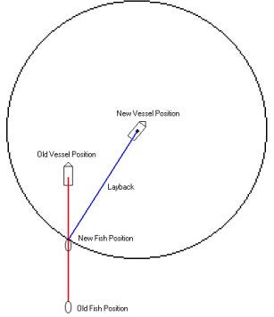
As the vessel moves ahead, a new circle is generated. The intersection of the circle and the track of the fish is then computed as the new position of the fish. The heading of the fish is the azimuth from the fish to the boat. We are still fine tuning the calculations to get a more accurate position of the fish. At this point I am much happier about the location of the towed object tracking and would recommend this method over the previous method of calculating the layback position.
If you would like the new driver I can either e-mail it to you or it can be obtained by downloading the latest Service Pack from the internet.
Below I have included a sample image of a screen capture showing both the old and new methods of tracking a towed object. This is a worst case scenario and was meant to show a dramatic effect of layback.
Q曳航体用ケーブルドライバの使用報告(Towcable.dll -- A Report from the Field)
FAQ ID:Q17-5
Tow cableドライバは曳航器のより正確な位置計算を可能とするドライバです。このドライバは何人かの客先でテストし、MYPACK Maxを用いたより良い曳航器のトラッキング理論として完成しました。
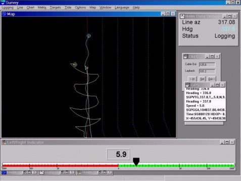
下記の例は実際のテスト結果です。この図によりトラッキング性能が分かると思います。
上の図で青い線は船の位置で、赤い線が方位を用いて計算された曳航器の位置です。このテスト、及び他の幾つかのテストによりこの理論が曳航器の位置計算に最も適していると言えるでしょう。
HYPACK Maxで2つのラインを画面上に同時に表示するためには以下の手順を踏んでください。
- まずHYPACK MaxのCONTROL PANELを開いてください。これはSETTINGメニューからCONTROL PANELを選択、または鐫と金槌のアイコンをクリックしてください。
- タブからTrack Linesを選んで下さい。イメージは以下の図のとおりです。
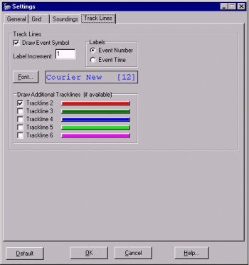
- ここでユーザ側が全てのトラックラインについて、表示、非表示等の変更を行えます。それぞれのトラックラインの色は変えることが出来ませんが、Main Vesselの色のみ、Fontボタンで変えることができます。
Q曳航体の航跡処理(Towcable.dll)[英語]
FAQ ID:Q17-4
During a recent training session, the towed object tracking in Hypack® was discussed with several of the Hypack® users in the class. The problem with monitoring a towed object such as a magnetometer or side scan has always been trying to approximate the actual track of the object in relation to the vessel towing the object.
After investigating the method used, a decision was made to improve the track of the towed object by using the course made good as a reference to the actual heading of the object. This worked better, but was found to be lacking a bit in the expected track of the object, so we have written a new algorithm to calculate the position.
As the vessel moves ahead, a new circle is generated. The intersection of the circle and the track of the fish is then computed as the new position of the fish. The heading of the fish is the azimuth from the fish to the boat. We are still fine tuning the calculations to get a more accurate position of the fish. At this point I am much happier about the location of the towed object tracking and would recommend this method over the previous method of calculating the layback position.
If you would like the new driver I can either e-mail it to you or it can be obtained by downloading the latest Service Pack from the internet.
Below I have included a sample image of a screen capture showing both the old and new methods of tracking a towed object. This is a worst case scenario and was meant to show a dramatic effect of layback.